If you’ve ever spent time on a commercial building construction site, you’ve probably seen cable trays—those metal or fiberglass channels that look like oversized, sturdy shelves running along walls, ceilings, and under floors. For a lot of people new to electrical or infrastructure work, these trays might seem straightforward enough: they hold wires, keep them organized, and prevent damage from foot traffic, dust, or accidental impacts. But the part that trips up even seasoned installers sometimes is connecting different sections of cable tray systems. I’ve been in the cable tray supply business for 12 years, and I can promise you this: a poorly connected cable tray section isn’t just an eyesore. It’s a safety hazard, a maintenance nightmare, and it can lead to costly downtime for whatever building relies on that system. Cable Tray Systems
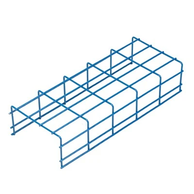
Let me start with why connecting cable tray sections correctly matters more than you might think. Think of the entire cable tray system as a single, unified pathway, not just a series of separate channels bolted together. For one thing, cable trays need to be grounded properly to meet electrical codes—bad connections mean inconsistent grounding, which can cause electrical shocks, interfere with sensitive equipment, or even spark fires. Then there’s structural integrity: if sections aren’t connected right, a long run of tray might sag under the weight of all the cables inside, pulling wires tight, fraying insulation, or causing the entire system to shift out of place. Add to that the fact that modern buildings often use hundreds of feet of tray, running around corners, up stairwells, and across open ceilings, and you can see how one wrong connection can derail an entire project.
Over the years, I’ve worked with installers, electricians, and general contractors on projects ranging from small retail spaces to large hospital complexes. I’ve seen every kind of connection mistake: sections aligned crookedly with gaps big enough to damage cable sheaths, bolts left loose so the tray rattles when someone walks by, and even using the wrong hardware entirely because a supply warehouse sent the wrong part. Today, I’m breaking down the most common, reliable ways to connect different cable tray sections, along with tips I’ve picked up from years in the field to make sure your next connection holds up.
First, it helps to know that not all cable trays are the same, and the connection method you use will depend on what material your tray is made of, what type of tray it is, and what environment it’s going in. For example, galvanized steel trays are common for indoor, low-corrosion areas, while aluminum trays are lighter and work well for outdoor or marine environments. Fiberglass reinforced plastic (FRP) trays are a newer option for places with high moisture or corrosive chemicals, like food processing plants or wastewater facilities. Each of these materials uses slightly different connectors, so always check the manufacturer’s guidelines before you start.
Let’s start with the most basic connection: straight section to straight section, aligned in a straight run. For standard steel and aluminum trays, the go-to here is a splice plate, also called a connecting plate. This is a flat piece of the same material as your tray, sized to cover the gap between two end sections. Here’s how it works: first, you need to make sure the ends of the two tray sections are cut clean and square. Even a tiny uneven cut can create a gap that lets cables catch, so use a metal saw or angle grinder with a fine-tooth blade to get a smooth, straight edge. Next, hold the two sections tightly together, so they’re level and flush with each other—no steps or bumps between them. Then, line up the splice plate over the inside of the tray, running the entire length of the gap. You’ll need two splice plates for most standard tray: one on the inside of the tray channel, one on the outside, to hold it securely. Now, you’ll use fasteners that are rated for the tray material—for steel, usually galvanized steel bolts and nuts, and for aluminum, stainless steel fasteners to prevent galvanic corrosion, which happens when two different metals touch and cause rust. I always recommend using carriage bolts for splice connections because the round head sits flat against the tray, so it won’t catch on cables as they’re pulled through. Tighten the bolts evenly, not cranking one all the way down first—this helps keep the tray aligned and prevents warping.
For tray runs that turn a corner, whether 90 degrees for a wall or 45 degrees for a sloped run, you’ll use what’s called an elbow, or a corner fitting. A lot of installers make the mistake of trying to cut straight tray sections to make a corner, and while that works in a pinch, it’s not as reliable as a pre-fabricated elbow. Pre-made elbows are engineered to fit perfectly with standard tray sections, so they create a smooth, continuous channel for cables, which reduces damage during pulling and makes future maintenance easier. When connecting an elbow to a straight section, the process is almost the same as a straight splice: make sure the ends are cut square, align the elbow and straight section flush, use the same splice plate and fastener method, and torque the bolts to the manufacturer’s recommended setting. One thing to remember here is that if you’re running tray through areas where it might be exposed to heavy wind or vibration, like an outdoor rooftop, adding extra fasteners at the corner connection helps keep the tray from shifting.
What about connecting tray sections that run at different elevations, like going up a floor or down a stairwell? For that, you use offsets, or riser fittings. An offset lets you adjust the height of the tray run smoothly, without creating a sharp bend that would make pulling cables hard. Connecting an offset to straight sections follows the same basic steps as a splice or elbow, but there’s an extra consideration here: the angle of the offset. Most offsets come in standard angles, like 15, 30, or 45 degrees, so make sure you pick the right one for your elevation change. A 45-degree offset is good for small height changes, while a 15-degree offset works for larger, gradual changes to avoid putting too much strain on the tray or cables.
Now, if you’re working with FRP trays, the connection process is a little different. FRP is non-metallic, so galvanic corrosion isn’t a concern, but the material is lighter and more brittle than metal, so you have to be careful not to overtighten fasteners. For FRP tray connections, most manufacturers recommend using specialized FRP splice plates and fasteners, designed to grip the plastic without cracking it. You’ll still cut the ends of the tray square, align the sections, and use both inside and outside splice plates, but instead of metal bolts, you’ll use stainless steel or plastic screws that are rated for FRP use. I’ve seen installers use regular metal screws on FRP trays, and they end up stripping the plastic or splitting the tray when they tighten them, so it’s worth buying the right hardware for the material.
A huge part of connecting cable tray sections correctly is following code requirements. Most electrical codes, like the National Electrical Code (NEC) in the United States, have specific rules for cable tray connections. For example, NEC 392.21 requires that all cable tray sections be securely connected and grounded, so the entire system is a continuous electrical path. That means you can’t just rely on mechanical fasteners for grounding—you might need to add a grounding jumper, especially for long runs or areas with high electrical load. A grounding jumper is a short length of copper wire, usually 6 AWG or larger, connected between two adjacent tray sections, bolted to the metal surface. This ensures that even if the splice plate or fasteners become loose, there’s still a clear path for electricity to ground, preventing shocks. Always check the local electrical code for your project, and if you’re not sure, consult a licensed electrician—cutting corners here is never worth the risk.
Over the years, I’ve picked up a few field tips that make connecting cable tray sections faster and more reliable, which I always share with the installers who buy our products. First, always pre-fit your connections before tightening anything down. Hold the tray sections, elbow, or offset in place, dry fit all the splice plates and fasteners, and make sure everything lines up correctly before you start tightening. This saves you from having to cut or reposition sections mid-install, which is a huge time-saver on tight deadlines. Second, keep a set of tools on site that’s dedicated to cable tray work: a square to check that cut ends are straight, a torque wrench to make sure bolts are tightened to the right setting, and a variety of fasteners so you don’t have to run back to the supply warehouse mid-job. Third, for long tray runs, mark the sections with a permanent marker before you connect them. Not only does this help you keep track of where you are in the run, but if you ever need to add or remove a section later, you’ll know exactly how everything was aligned.
I also want to talk about a common mistake I see all the time: using incompatible parts. For example, if you have 6-inch wide tray, using a splice plate made for 4-inch wide tray won’t fit, and if you force it, you’ll end up with a loose, unsafe connection. Or using steel fasteners on aluminum trays—even if they look the same, steel and aluminum react when they touch, leading to corrosion that weakens the connection over time. This is why working with a reliable cable tray supplier is so important. We don’t just sell tray sections; we make sure every connector, fastener, and fitting is designed to work with the exact tray sizes and materials we provide, so you don’t have to guess if a part will fit or work.
At the end of the day, connecting cable tray sections is about creating a system that works as a whole. A tray that’s connected correctly will hold up to the weight of hundreds of cables, last for decades, and keep your building safe and compliant. It’s not the most glamorous part of a construction project, but it’s one of the most critical.
If you’re working on a project and need the right cable tray sections, connectors, or fasteners, we’ve got you covered. Our team has years of experience in the cable tray industry, and we can help you pick the right materials for your specific needs—whether you’re working on an indoor office, an outdoor industrial facility, or a specialized space like a hospital or food processing plant. We also provide detailed installation guidelines for every product we sell, so you have all the information you need to connect sections correctly the first time.

Don’t let bad cable tray connections turn your project into a safety hazard or a maintenance headache. Reach out to us today to discuss your cable tray system needs, and let our experts help you get it right.
Cable Tray References
- National Fire Protection Association. (2023). National Electrical Code (NEC) Article 392: Cable Trays.
- Underwriters Laboratories Inc. (2021). Standard for Safety for Cable Trays (UL 20).
- Manufacturing Engineers Society. (2022). Cable Tray Installation Best Practices and Standards.
Hebei Jinglang Industrial Co., Ltd.
As one of the most professional cable tray systems manufacturers and suppliers in China, we also support customized service. We warmly welcome you to wholesale high quality cable tray systems in stock here from our factory. If you have any enquiry about quotation, please feel free to email us.
Address: Nanxinzhuang Village, Daweihe Hui and Manchu Township, Wen’an County, Langfang City, Hebei Province
E-mail: 18231629992@163.com
WebSite: https://www.jinglangcabletray.com/
